
Nádherná práce a tak vlastně ukázka hezké porce řemesla :)
Telescopic spool holder for CTX 3030 - workflow
Categories: Minelab CTX 3030 metal detector
First a few general notes - this guide is for inspiration only and everyone will find room for their own modifications or simplifications. During the production of the prototype, emphasis was placed on maintaining the original quality of the Minelab guide rod design as the CTX 3030 certainly deserves J. That is, no metallic structural elements were used, and an effort was made to maintain minimum manufacturing tolerances so that the rod, when unfolded, would be rigid and free of play (uncomfortable wobble in use). All elements were, as with the original, made of carbon composite. The standardised structural elements (metric bolts, nuts, washers) are made of polyamide (PA) or glass fibre filled PA (available e.g. at www.plastovesoucastky.cz/) .
Carbon composite is an excellent construction material, lightweight yet strong, and sufficiently electrically non-conductive for our application. However, its machining has some specifics, so I will give some of my experience here. They may save the disappointment of devaluing a rather expensive material:
- Cutting - the material can be done with an ordinary hacksaw, with fine teeth. The blade of the saw should be sharp. Do not put any pressure on the saw, cut very gently!!! /Cut "around the perimeter", i.e. rotate the workpiece./ Otherwise, the material is cut out and the fibres are separated from the composite. Care should also be taken when re-cutting the profile to avoid breaking the material. The cutting surfaces can be sharpened with a high quality abrasive cloth of 200-300 grit.
- Drilling - at higher speeds (even 6.5 mm at approx. 2800 rpm), with slow feed. Drill gently, do not apply pressure to the drill bit! Optimally, the workpiece should be backed with hard wood on the other side.
- Milling - is possible with carbide-tipped milling cutters designed for top wood milling machines. However, always mill on a cross-feed milling machine with a small footprint (up to 0.5 mm). Select the highest possible speed (2800 - 3000 rpm). Same as for drilling.
- Turning - is possible using knives with carbide inserts. Forged blades or blades made of RADECO steel dull very quickly, their use is practically impossible (possibly due to the admixture of glass fibres in the composite). Even knives with carbide slices must be kept sharp at all times, or sharpened during the work. Turn at lower speeds (up to 500 rpm) with low material removal (up to 0.25 mm).
- Gluing - it is possible to use two-component glues (epoxies). I recommend those designed for strength joints, and prefer to avoid the fast-setting types (they force you to work in a hurry and the joints tend to be brittle). The glued surfaces should be sanded perfectly. Both the smooth outer surface and the inner surface of the pipes. In order to make the joint strong, it is necessary to remove a layer of varnish from the outer part, or conversely a layer of material from the inner part, which is saturated with a separator (as a matter of manufacturing principle, so that the tube can be removed from the laminating mandrel)...
And now to the modifications made:
- It is certainly good to be able to return the detector to its "original state". It is therefore advisable to use spare parts - the guide rod assembly - (purchased at lovecpokladu.cz, whom I would like to thank for this!) and keep the original one.
- Cut 435 mm from the lower part of the guide rod towards the positioning moulding. From the side of the coil holder, 220 mm (measured from the centre of the coil fixing screw) - see "07-assembly_kotovano.jpg"
- For the middle part "C" , 445 mm long, a carbon composite tube with an outer diameter of 24.8 mm was used. This is because with an inner diameter of the tube Minelab of 25.3 mm there is still some space for the centering sleeves, which back up theThis also serves as a stop so that part "C" cannot be slid out of part "B" during normal handling. /Note: Those who do not mind the larger difference between part "B" and part "C" can use a 24 mm OD tube, the centering sleeves will be easier to produce. Or, on the contrary, who does not mind that part "C" could be slid out of part "B" even towards the front, can use a pipe with an outer diameter of 25.0 mm. For centering, a strip of very fine glass fabric (or paper, in a pinch, well impregnated with resin) 50 mm wide can be laminated to the end of the tube and wrapped with a strip of smooth PE film until it cures. Then sand the extension (e.g. with a strip of abrasive cloth, partially encircling the radius of the tube) to the outer diameter so that it can be inserted into part 'B'. / In the case of the prototype, the following tube was used: https: //www.topmodelcz.cz/index.php?&desktop_back=eshop&action_back=&id_back=0&desktop=eshop&action=zbozi_detail&id=207373 . However, in this particular piece the tube was tapered towards the end, so it was necessary to cut off about 150 mm first. The diameter should be checked along the entire length of the intended part "C" with a digital caliper so that it does not vary by more than 0.1 mm. The tube can also be purchased on aliexpress.com (search for "carbon tube 25 mm"), I recommend the circumferentially ground version (it has a constant diameter, it will not scrub when the telescope is unfolded). A wall thickness of 1mm is sufficient.
- From the carbon tube 26/24 mm ream out two centering sleeves with l = 25 mm - see item 2 on "12-draw.jpg". Due to the small wall thickness it is necessary to turn on a mandrel of the appropriate size.
- Glue one bushing into part "B", the other one onto part "C".
- The bushings should be welded together so that the parts fit together (without unnecessary clearance). The sleeve glued into part "B" should have a certain clearance /about 0.1..0.2 mm - when the clamp is removed, the clearance is defined/ in relation to the pipe "C", otherwise its surface will be scratched even by fine dust. On the other hand, the sleeve glued on the outside of pipe "C" should be inserted into pipe "B" without unnecessary clearance.
- From the 26/24 mm carbon tube, ream the centering sleeve with l = 55 mm - see pos. "2" on "12-res.jpg"
- Glue this sleeve into part "D". /Note: In case of using a pipe with an outer diameter of 25.0 mm - see above - points 6) and 7) can be omitted.
- Use a carbon rod (solid material) with a diameter of 16 mm (also purchased at topmodel.cz ) to make the lock blanks (clamps) - see pos. "(Instead of carbon composite, it is also possible to use another, cheaper, epoxy adhesive material. Depending on the intended use with regard to non-absorption, choose e.g. textite, cartite, bakelite, epoxy resin castings or elements modelled from two-component putty, or even beech wood saturated with epoxy resin, etc.)
- Glue these blanks to parts "B" and "D", 5 mm from their end - see "09-lock_detail_anchored.jpg". Pay attention to their orientation relative to the positioning sprue on tube "B" and the axis of the clamping screw in the case of part "D". The locks and sight cutting edges on tube "B" and "D" can be painted with epoxy varnish or epoxy glue, diluted with acetone, for better appearance and mechanical resistance.
- Optimally, on a boring mill, clamp parts "B" and "D" in a vice fixed to the cross feed, center the 4.8 mm hole of the clamp blank against the drill bit, and drill with a drill bit pr. 6,5 mm to a depth of 16 mm. At this point we can decide which side we want the clamp control on, and drill from that side accordingly. For the prototype, the clamp control was chosen to be on the left side.
- Cut an M6 thread into the lock blanks (into the remaining approx. 10 mm).
- Drill a 4 mm diameter hole in parts "B" and "D" in the axis of the lock, 40 mm from the edge.
- Cut parts "B" and "D" on a milling machine with a saw blade approx. 0.8 mm thick. (For precise work, even 0.6 mm is sufficient, as in the case of the prototype, but in case of emergency, cutting with a hacksaw is sufficient).
- Screw the PA screws M6 x 40 into the clamps, then screw the PA nut M6 (knurled version with a diameter of 13 mm) on the other side over the PA washer - see pos. "3" on "12-drawings.jpg". By tightening the nut, the clamp is tightened and the telescopic holder is stiffened.
- Drill a 3.2 mm hole in the bottom part "D", 52 mm from the edge and cut out the M4 thread. Screw in the PA screw M4 x approx. 4 mm. This serves as a stop, limiting the insertion length of part "C" into part "D" to 50 mm.
- Who finds the bend of the cable from the coil when passing through the lower original grip too sharp and has therefore worried about damaging it (like me) can mill the hole in the bottom part according to "07-assembly_anchored.jpg". A 12 mm diameter cutter was used. Before milling, I "secured" the plastic holder against the pipe with another PA screw M4.
- Finally, cut the square profile "Minelab" to a length of 400 mm (part "A"). Attention! The cut-outs for the lever lock must be retained, cut from the opposite side.
- Replace the cut square profile with the original one. The cut-out for axial fixation in the plastic holder must still be cut into it. This is cut out after disassembling the holder and inserting the prepared 4hr blank. After reassembling the handle assembly, reassemble the lever lock (can be disassembled after pushing out the center steel pins).
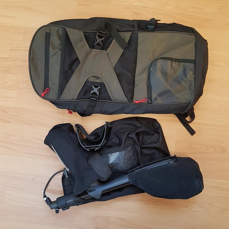
When the holder is inserted and the 11" coil is used, the total length of the detector is about 89 cm (see "03-view_3.jpg", the perspective in the photo distorts the dimensions a bit), when the detector is folded according to "06-view_6.jpg" the dimensions are about 31 x 55 cm, so the detector in this state can be carried in a suitable backpack quite comfortably. And that was the original intention of this design - to achieve more compact dimensions of the detector for transport, without the need to de/mount the connectors in the terrainin addition to slightly uncomfortable handling, there is a risk of contamination or damage with a consequent negative impact on the function of the detector.

Tap to enlarge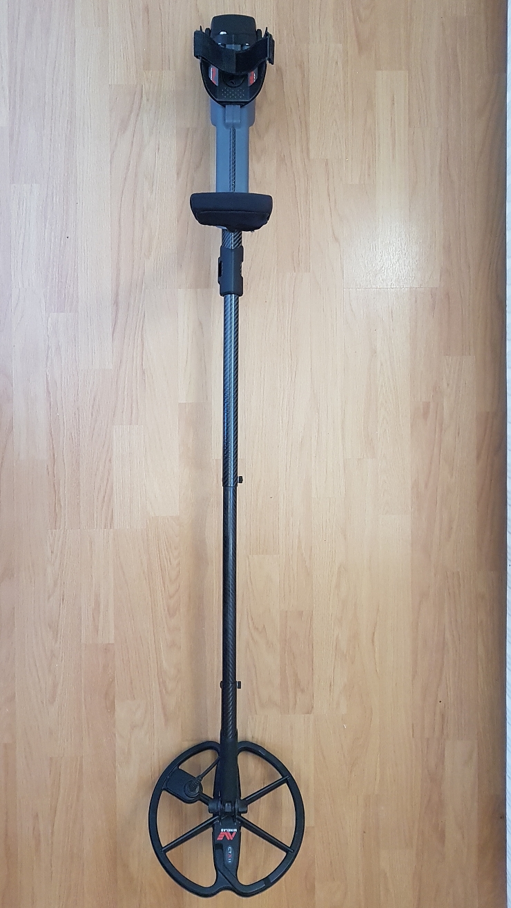

Tap to enlarge


Tap to enlarge


The article is included in categories:
- Archive of articles > Metal Detectors - Reviews and Tests > Minelab – tests and reviews > Minelab CTX 3030 metal detector
Post


Jako ukázka na téma „Zlaté české ručičky“ to nemá chybu a moc se mě to líbí.
Ale zcela realisticky - kolik zdejších lovců bude schopno dodržet celý technologický postup? Já myslím, že prsty na rukou nám ke spočítání postačí.
Jsem kolego také strojař a z toho pohledu na to také nahlížím.
Ale jinak parádní teleskop. A i kdyby jen jeden jediný člověk, tento článek s perfektně odvedeným popisem použil, splnilo to svůj účel.


Pěkná práce 
Bude jich více Romane. Jenom ty co vědí, že živit se rukama je pro ně nebezpečné, si to nechají udělat. .)
Připomnělo mi to Marku dobu, kdy ve všech fabrikách frčel časopis: Udělej/urob si sám.
Tam byly přesně takové návody, včetně detailních postupů a rozpis všech potřebných dílů do posledního šroubečku.
Tenhle návod je jak ze zmíněného časopisu. Dobrá nostalgie 

Precizní práce, všechna čest šikovným rukám
To namor: ty časáky tam byly proto, že všichni v těch fabrikách kradli jako straky. A všechno se dělalo z "eráru". Ještě jsem závěr tohoto období zažil na Julisce, kde od rána vrčely dva soustruhy, vrtačky atd. Tam to vypadalo, že všichni padají na hubu jak se musí pro tepláránskou dřít. Jenom že všichni dělali fušky a takový Hruška si tam udělal přímo živnost na čerpadla. Tomu tam chodili ty chataři s ponorkama přímo na plac a rovnou se to tam domlouvalo :).
Na údržbě jsem tam pracoval co by technik MaR rok, tedy pracoval. Každý den jsem dělal tak hodinu a to do toho počítám i donášku svačiny pro parťáka :). Pak mě to přestalo bavit šel jsem dělat ven.
Tak tolik k té nostalgické chvilce :)
Ano, jako straky, taková byla doba.
Dnes se ve fabrikách krade ještě víc, ovšem zcela na jiných pozicích. Mnoho fabrik tihle zloději bez monterek poslali do kopru. Taková je doba
Nad tím se nemělo brečet, ale mělo se to stíhat. Scénář byl vždy stejný. Soudruh ředitel, který by celé roky věrný straník, si na začátku 90tek udělal nějaké vlastní s.r.o. A do něho postupně převedl všechno co v továrně za něco stálo. No a tu prázdnou obálku pak nechal spadnout do konkurzu.
Řada těch firem je stejně pryč, jelikož soudruh zůstal soudruhem a prostě to poslal do kopru stejně, jelikož byl ekonomický v 70sátkách a idiot. Co fungovalo daleko lépe, byly přímé prodeje, jako byla Škodovka. Ne vždy, ale bylo to o hodně lepší. Dns když se podíváš kdo tady odvádí největší daně, jsou to právě tyhle firmy Naštěstí jsou tady i nové společnosti, postavené na zelené louce, jako třeba Jablotron nebo antivirové firmy atd.
To co se ukradlo už asi nevyřešíme a jeden z těch "nejlepších takových borců" tady 8 let vládnul. Možná bude sedět i na hradě. Na to se moc těším....
Velká pravděpodobnost, že se tam nakonec uhnízdí.
A ano, škoda plakat nad rozlitým mlékem.